この時代の論文は、電子サイクロトロン波による電流駆動に焦点を当てており、ティアリングモードと関連づけて議論されている。代表的な論文は「Currents driven by electron cyclotron waves」と「Current drive by electron cyclotron waves and tearing-mode configurations」であり、波と電流駆動の関係を初期段階から探るものであった。
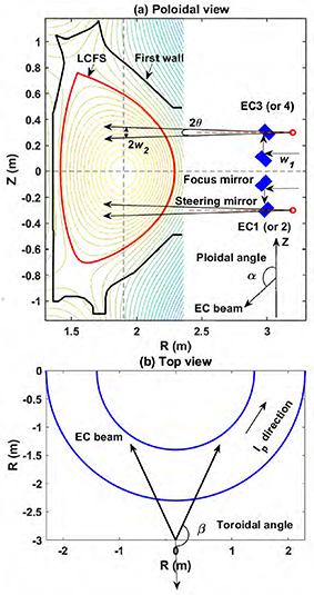
Configuration of EC system (composed of four RF units) in the poloidal (a) and the top views (b). The launcher mirrors are denoted by the blue rectangles. In the range of the plasmas (R = 1.4–2.3 m, corresponding to 1.6–0.7 m from the steerable mirror), the divergence of the Gaussian beam is fitted to a cone with a divergence of θ = 1.79° at e−1 of the electric field amplitude with a starting point of R = 3.2 m (0.2 m behind the steerable mirror, as indicated by the red circle). w1 (∼18.9 mm) and w2 (∼40.7 mm) are the beam vacuum waist sizes at the circular corrugated waveguide and at R = 1.9 m near the magnetic axis, respectively. The definition of the poloidal injection angle (α) and toroidal angle (β) of the EC beams is shown.
Calculated EC power density profiles for discharges #139 689, #139 691 and #139 693 with slightly different Bt0. The poloidal (α) and toroidal angles (β) are [103°, 200°] and [77°, 200°] for EC3&4 and EC1&2, respectively. Ray trajectories in the poloidal plane are computed by the ray-tracing code C3PO. The thick black lines show the absorption region and the vertical red lines represent the cold resonant layers.
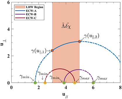
The resonance curves of ECW and the diffusion region of LHW in velocity space. The meaning of each point is marked in the figure. The different color lines denote different CD cases: ECW-A(y = 0.95, n_{\parallel} = 0.4), ECW-B(y = 0.92, n_{\parallel} = 0.4), and ECW-C(y = 0.958, n_{\parallel} = 0.3). The LHW diffusion region is fixed at a range of 3u_\mathrm {e} to 5u_\mathrm {e}.
図は、速度空間(平行速度 u と垂直速度 u の平面)で、EC 波の共鳴曲線と LH 波の拡散領域の位置関係を示したものである。EC 波の周波数と平行屈折率 n の選び方(ECW-A, B, C)によって共鳴曲線が LH 波領域(帯の部分)にどのように接するかが変わり、相乗効果の有無や大きさが決まる。

![Calculated EC power density profiles for discharges #139 689, #139 691 and #139 693 with slightly different Bt0. The poloidal (α) and toroidal angles (β) are [103°, 200°] and [77°, 200°] for EC3&4 and EC1&2, respectively. Ray trajectories in the poloidal plane are computed by the ray-tracing code C3PO. The thick black lines show the absorption region and the vertical red lines represent the cold resonant layers.](https://fusionpapers-figures.s3.ap-northeast-1.amazonaws.com/nfadddcaf4.jpg)